
1.Brief learning about the helical planetary gearbox
A helical planetary gearbox is a speed reducing transmission system that combines a planetary gear arrangement with helical gearing teeth cut at an angle to the gear's axis rather than straight across. The helical teeth engage gradually and simultaneously over a larger contact area, delivering smoother torque transmission, lower noise, higher load capacity, and greater precision than conventional spur tooth planetary gearboxes, all while retaining the planetary design's compact footprint and high torque density.
2.Main types of helical planetary gearboxes
1.Inline Helical Planetary Gearboxes: The most common type where the input and output shafts are aligned in a straight line. They are widely used for general industrial machinery like mixers and pumps.
2.Right Angle Helical Planetary Gearboxes: These combine planetary stages with bevel gears to transmit motion at a 90 angle. They are ideal for space constrained layouts in robotics and conveyors.
JESSICA 發表在
痞客邦
留言(0)
人氣()

1.Brief learning about CNC motion controller
A CNC motion controller is the core computing and command generation unit of a Computer Numerical Control system. It interprets part programs, executes mathematical interpolation, and generates coordinated, real time motion commands for the machine's axes. Unlike a general purpose computer, a motion controller is specifically optimised for deterministic timing, multi axis synchronisation, and seamless integration with servo drives and I/O devices.
2.Working principles of CNC motion controller
1.Instruction interpretation:It reads and parses G code/M code programs input by the operator or CAD/CAM software, identifying target positions, feed rates, machining paths, and auxiliary commands.
2.Trajectory planning:Based on the machining program, the controller calculates smooth motion paths using interpolation algorithms. It computes real time coordinate points for each axis to ensure continuous and accurate contouring.
JESSICA 發表在
痞客邦
留言(0)
人氣()

1.Core definitions of manual linear stage
A manual linear stage is a precision mechanical component designed to restrict an object to a single axis of linear motion, realizing accurate position adjustment and stable movement through manual operation rather than electrical or hydraulic drives. It is a key part of precision positioning systems, which constrains the moving platform to only one degree of freedom by limiting three rotational axes and two other translational axes, ensuring that the load moves stably and accurately along a preset linear path.
QMF90
2.Working steps of manual linear stage
1.Mount the stage:Clean the mounting surface.Position the stage so its axis of motion aligns with your required direction.
JESSICA 發表在
痞客邦
留言(0)
人氣()

Aservo motoris an electric actuator that operates as part of a closed-loop system. It includes a feedback mechanism—typically a sensor such as an encoder—that continuously reports the motor's actual position or speed to a controller. This allows the system to adjust its output until the desired state is reached.
When a command is sent, an electrical signal moves the output shaft to a specified angle, position, or velocity. The feedback device confirms whether the target has been achieved, and corrections are applied as needed.
Servo motors operate within a closed-loop system, meaning position and speed are continuously monitored and adjusted. In contrast, open-loop systems execute commands without verifying the final position.
A typical servo motor consists of a standard DC or AC motor combined with a feedback sensor and a control circuit. The control circuit interprets input signals and drives the motor accordingly.
JESSICA 發表在
痞客邦
留言(0)
人氣()

Brushless DC motorsoperate using electronic commutation rather than mechanical brushes. This design affects how they are powered and controlled. To run a BLDC motor, a controller is required to manage the electrical signals that regulate speed, direction, and torque.
When choosing both components, a few basic specifications determine compatibility with your application.
Motor Specifications
Speed and torque are two primary performance characteristics. Each motor has a rated speed range and a continuous torque output. When these match the mechanical demands of an application, the motor operates within its design limits.
JESSICA 發表在
痞客邦
留言(0)
人氣()
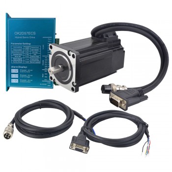
1.What is a closed loop stepper motor?
A closed loop stepper motor is a stepper motor system that incorporates a feedback mechanism, typically an encoder, to monitor its position and correct for any deviations from the intended movement. This feedback allows the motor to operate more reliably and accurately than traditional open-loop stepper motors, especially under varying loads or at high speeds.
2.The introduction of closed loop stepper motor working principle
Closed-loop stepper motors enhance precision by using feedback to correct for any deviation from the intended movement. An encoder monitors the motor's position, and this information is relayed back to the controller. If a discrepancy exists between the desired and actual position, the controller adjusts the motor's operation to compensate, preventing lost steps and improving accuracy, especially under varying loads.
JESSICA 發表在
痞客邦
留言(0)
人氣()
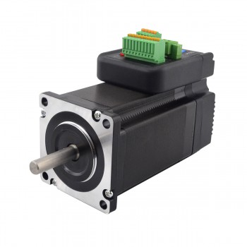
1. Basic definition and function of integrated servo motors
Integrated servo motors integrate key components such as servo motor body, encoder, and driver to form a complete servo system. This design not only simplifies the installation and maintenance of the system, but also improves the reliability and response speed of the system. The encoder is used to detect the position and speed of the motor in real time, and the driver is responsible for receiving the control signal and driving the motor to rotate, thereby achieving high-precision position, speed and acceleration control.
2. Working principle of integrated servo motors
The working principle of integrated servo motors is based on a closed-loop control system. The system detects the position and speed of the motor in real time through the encoder, compares the detected actual value with the target command value, and adjusts the input of the motor (such as current, voltage, frequency, etc.) according to the comparison result, so that the actual output of the motor is infinitely close to the target command value. This closed-loop feedback mechanism ensures high-precision control and high dynamic response of the motor.
JESSICA 發表在
痞客邦
留言(0)
人氣()
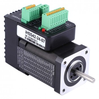
1. Basic definition of closed-loop stepper motors
A closed-loop stepper motor is a stepper motor that adds an encoder to the stepper motor to achieve high-precision, low-jitter functions through position feedback and speed feedback. The closed-loop stepper motor detects the actual position and speed of the motor, compares it with the target position and speed, and adjusts the running state of the motor through the feedback mechanism, thereby ensuring that the motor's movement is more precise and stable.
2. Working principle of closed-loop stepper motors
The closed-loop stepper motor system is mainly composed of a stepper motor, a driver, and an encoder. The driver receives the control signal and drives the stepper motor to operate. The encoder monitors the position information of the motor in real time and feeds this information back to the controller. The controller uses the PID control algorithm to calculate the adjustment amount based on the deviation between the position information fed back by the encoder and the target position, and adjusts the running state of the motor through the driver to achieve higher positioning accuracy and more stable system performance.
JESSICA 發表在
痞客邦
留言(0)
人氣()
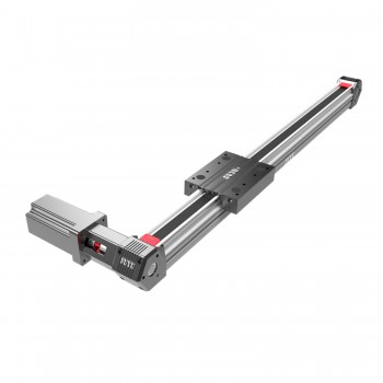
1.Definition and principle of linear guide rail
1.Linear guide rail is a mechanical component used to support and guide moving parts to reciprocate linear motion in a specific direction. It can achieve high-precision linear motion under high load and can bear a certain torque load. Its core principle lies in the design of its internal structure. It consists of components such as slide rails, sliders, balls, ball retainers, and return ball grooves. The balls roll and circulate infinitely between the sliders and the guide rails, allowing the load platform to move linearly along the guide rails with high precision. This design makes the friction coefficient extremely low, enabling subtle and precise motion to meet the needs of high-precision positioning.
2.Main structure of linear guide rail
1.Guide rail: The guide rail is the main load-bearing component of the linear guide rail, which usually has high hardness and wear resistance to ensure high precision in long-term use. The design of the guide rail can be box-shaped, round or other shapes, depending on the application requirements.
JESSICA 發表在
痞客邦
留言(0)
人氣()
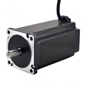
1. A brief introduction to hybrid stepper motors
Hybrid stepper motors are a type of motor that combines the advantages of permanent magnet stepper motors and reactive stepper motors. It has high output torque and high step accuracy, and is widely used in industrial automation and precision control, especially as a drive device in economical CNC machine tools. Its high precision, high reliability and good speed regulation performance make it perform well in these fields.
2. The main structure of hybrid stepper motors
The main structure of hybrid stepper motors includes three parts: stator, rotor and armature. The stator is usually composed of a combination of a reluctance winding and a wound winding of a traditional stepper motor. The stator is equipped with a multi-way winding structure and a permanent magnet on the periphery; the rotor is composed of a magnet and a small reluctance magnetic needle of a traditional stepper motor; the armature is composed of a regulating reluctance and a power supply, which is used to control the rotation direction and step of the motor.
JESSICA 發表在
痞客邦
留言(0)
人氣()
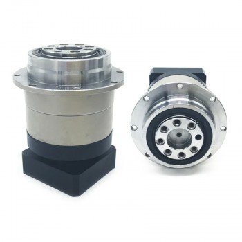
1. Introduction to helical planetary gearboxes
A helical planetary gearbox is a mechanical transmission device composed of a planetary gear mechanism and helical gears. The core lies in the layout of the planetary gears. The central sun gear is surrounded by multiple planetary gears, and the outer side of the planetary gears wraps around the annular gear ring, and all gear axes remain parallel. The characteristic of the helical gear is that the tooth shape is inclined at an angle to the axis, and the common angle range is between 15 degrees and 30 degrees. This design makes the gear meshing process more coherent and effectively reduces the operating noise and vibration amplitude.
2. Working principle of helical planetary gearboxes
The working principle of the helical planetary gearbox is mainly based on the combination of planetary gear mechanisms and helical gears. The core lies in the layout of the planetary gears. The central sun gear is surrounded by multiple planetary gears, and the outer side of the planetary gears wraps around the annular gear ring, and all gear axes remain parallel. The characteristic of the helical gear is that the tooth shape is inclined at an angle to the axis, and the common angle range is between 15 degrees and 30 degrees. This design makes the gear meshing process more coherent and effectively reduces the operating noise.
JESSICA 發表在
痞客邦
留言(0)
人氣()
1.A brief introduction to linear guide rail
Linear guide rail is a mechanical guide rail used to support and guide moving parts to reciprocate linear motion in a given direction. It usually consists of two parts: a track (slide rail) and a slider. The slider is equipped with internal circulation balls or rollers, which can achieve smooth, high-precision linear motion on the track and can withstand a certain load.
2.Components of linear guide rail
1.Guide rail: The guide rail is the main part of the linear guide, providing a track or path for linear motion. It is usually made of wear-resistant and high-strength carbon steel or alloy steel. 2. Slider: The slider is installed on the moving part and cooperates with the guide rail. The rolling body slides on the guide rail to achieve linear motion.
JESSICA 發表在
痞客邦
留言(0)
人氣()
